Sensor Wiring Setup

Tips for setting up a sensor and connecting directly to the Raspberry Pi/Multiplexer.
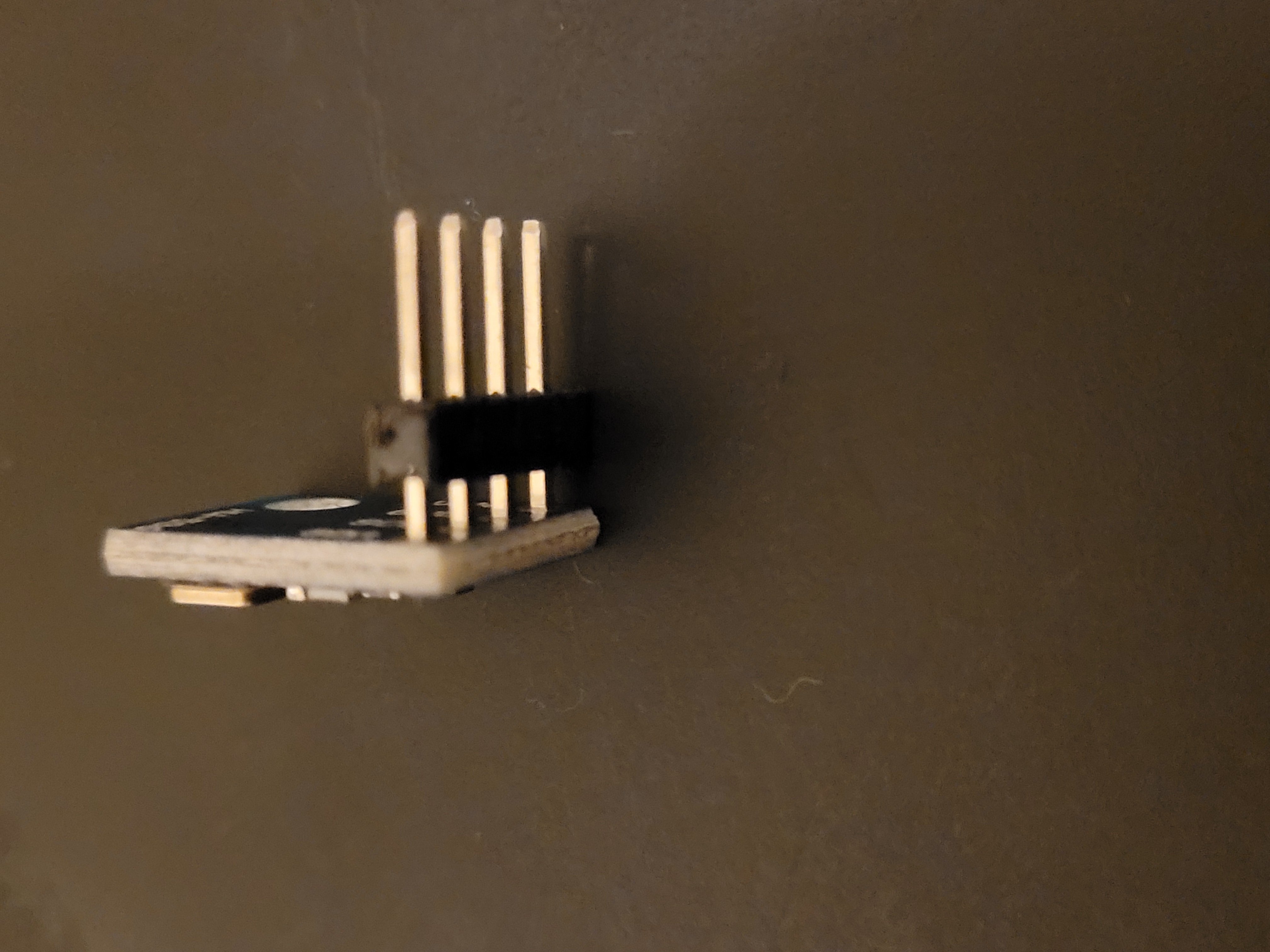
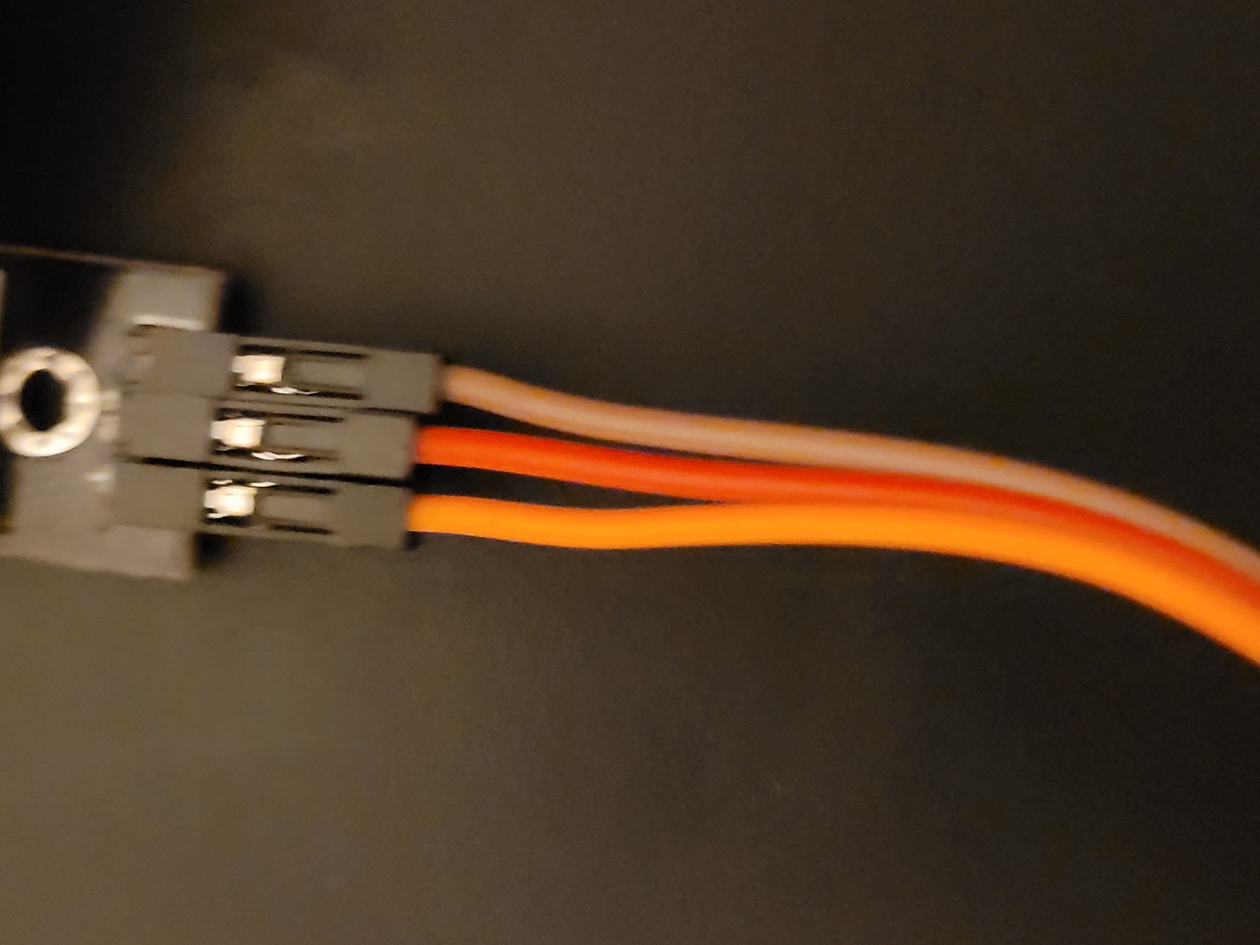
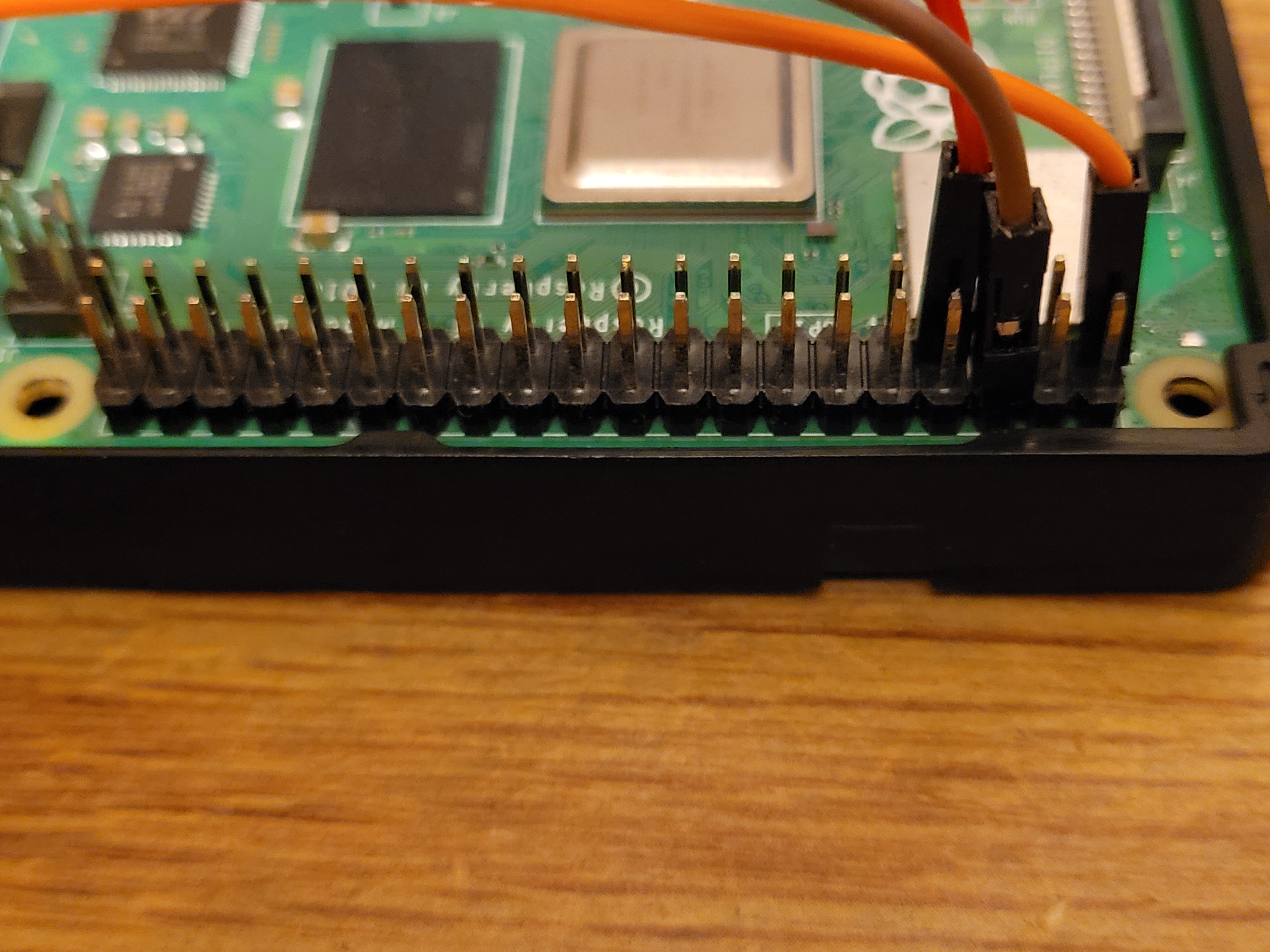
When connecting a sensor directly to the Raspberry Pi, there are a few things to keep in mind to successfully complete the task. The process can be very straightforward to complete, however likewise it can be very easy to mix up wiring and possibly even ruin the wiring on the sensor or GPIO pinouts on the Raspberry Pi. When connecting a sensor to the Raspberry Pi the first thing to check is the pin connections soldered to the sensor. These are the connections that, using wires, will provide power to the sensor while also transferring the necessary information between both connection points. If the sensor has no soldered pins (example below) or improperly soldered pins this can lead to connection issues as well as the possibility of "burning out" the pinouts. Once this step is completed you can then attach a female to female wire to the sensor. It is important to have the required number of wires, the wires are managed neatly and the wires are color coded. Neat management of the wires means the wires are not tangled nor are they too loose or too tightly connected to the Raspberry Pi. Proper length ensures the sensor can move freely with the rover but also the wire will not constantly be at risk of being easily pulled out. The color coordination helps the user identify what each wire represents and makes connection to the Raspberry Pi easier, as the three wires below show. The left orange wire connects to the 3.3v pinout for sensor power, the red center wire is used for the actual sensor information and the right brown wire connects to a ground pinout. Having this in mind then leads to a straightforward connection from the sensor to the Raspberry Pi as shown below. There are two 5.0v pinouts and are generally used for most sensors, as well as more intensive electronics such as servos. The 3.3v pinout is used for this particular sensor(DHT-22) as the power draw is low enough that the 3.3v or 5.0v is appropriate for usage. The ground wire completes the circuit alongside the power wire which allows the sensor to fully become a part of the circuit and allow power. The red wire is connected to a standard GPIO pinout and there are multiple such pinouts that can be used on the Raspberry Pi, however the number of connections besides the ground-power will dictate how many more connecctions will need to be made, as well as if any pinouts must be specifically connected. The process for connecting this sensor to the Raspberry Pi can be used for any other sensor and electronic to be used with the rover.